Oil-immersed Transformer Explosion-proof and Fire Protection Equipment is mainly used for the large oil-immersed transformer anti-explosion protection, fire protection, compared with the traditional oil drainage nitrogen injection system, water sprinkler or water mist sprayer system, can really play a role in preventing the transformer explosion, is more reasonable, more effective protection of the transformer anti-explosion and fire safety device.
Working Principle:
When large oil-immersed transformer encounters insulation fault, it is easy to produce arc discharge and local high temperature, which leads to the rapid decomposition of transformer oil and the production of a large number of combustible gas, resulting in the sudden increase of pressure inside the transformer. With the continuous rise of oil temperature, the risk of explosion and combustion of the transformer increases sharply.
Traditional water spraying or foam fire-fighting facilities can only be started the fire-fighting program after the transformer explosion or fire already occurred, which belongs to the 'fire-fighting' equipment after accident.
With the sharp increase of internal pressure of transformer, traditional pressure relief valve cannot effectively release the pressure quickly, so transformer is easy to suffer explosion.
The concept of this system is prevention explosion first, with effective fire prevention measures, before transformer suffering devastating destruction, rupture disk will be burst by internal high-speed dynamic pressure, high pressure will be released quickly, without any extra signal sensor nor any external driver.
After the rupture disk blasting, control system will start the nitrogen injection program at the first time to lower the temperature of the transformer main tank by nitrogen injection, at the same time, drive the gas inside the main tank and isolate the oxygen, effectively preventing the subsequent fire caused by high energy arc.
This Equipment can completely protect the transformer oil tank, on-load top changer and high and low voltage bushings respectively, so as to fully protect the transformer and deal with any faults.

· 2. Product Structure:
Transformer Explosion-proof and Fire protection Equipment(TEFPE) is composed of control cabinet (or control box), nitrogen storage Cabinet, Explosion-Proof Rapid Pressure Relief Device, oil drainage pipes, Oil And Gas Separation Tank, Shutter Valve, Fire detectors, Nitrogen Injection Pipeline, Gas Discharge Pipeline, Nitrogen Injection Pipeline, etc.
The following figure 1 is the typical configuration:
Horizontal Decompression Device for main tank, Fast Pressure Relief Device for OLTC.
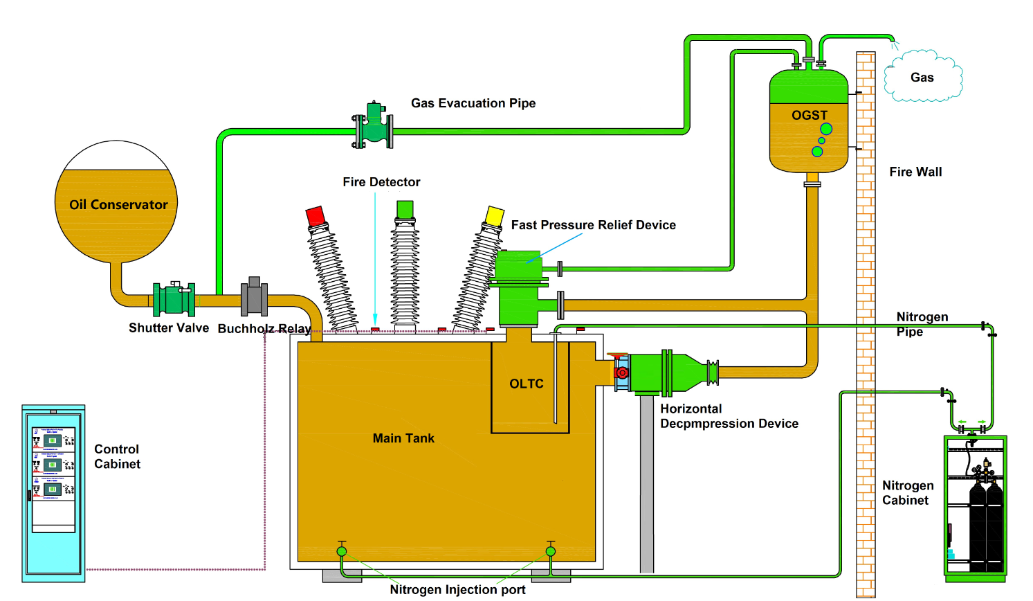
图1 防爆灭火保护装置(FB2型)结构示意图
Major Components
1 Shutter Valve
1) Being installed between Buchholz Relay and transformer oil conservator.
When evacuation, Shutter Valve will be closed by the fast oil flow to shut down the oil flow between oil conservator and main tank.
There is a glass window in the middle of the Shutter Valve to monitor the position of the valve at any time. Once the Shutter Valve is closed, the sound and light alarm will be issued. After finding out the cause, the valve can be reset manually.
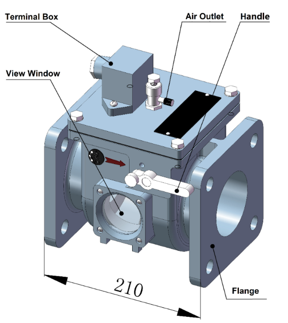
Figure 2 Shutter Valve
b). Technical Parameters :
Nominal Diameter: DN80
Nominal Pressure: 0.1MPa
Adaptive Temperature: -40℃~95℃
Flow of Shutting off: 0.3~0.5 m/s
Contact Rating: 20VA
c). Installation Instruction:
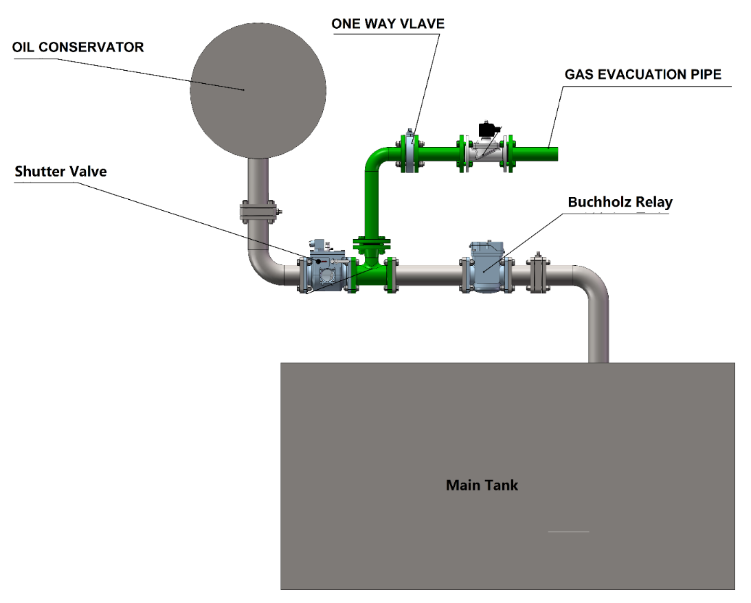
Figure3 Installation Instruction
2.2 Nitrogen Storage Cabinet
Nitrogen Storage Cabinet is installed near the transformer, 3 ~ 8 meters away from the transformer, which can be adjusted according to the actual situation.
Nitrogen Storage Cabinet is the actuator of the whole fire system, which injects nitrogen into transformer when receiving instructions from the control cabinet. Nitrogen Storage Cabinet is equipped with nitrogen storage cylinder, nitrogen release valve, nitrogen pressure reducing valve, nitrogen flow control valve, oil and gas isolation valve, low discharge and high sealing valve and nitrogen injection signal feedback valve and other devices.
Please see attached following drawings for the detailed structure of the cabinet:
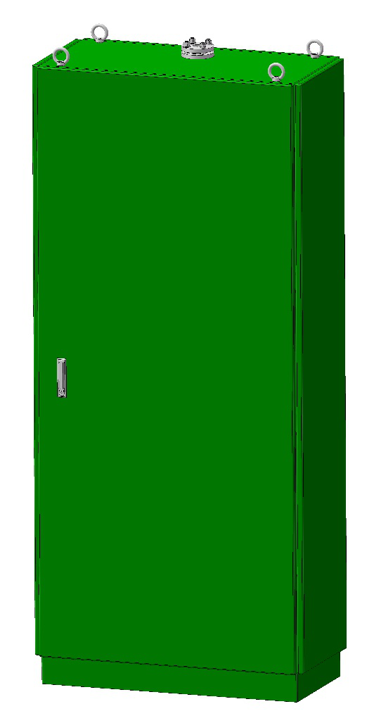
Figure 4 Nitrogen Storage Cabinet Diagram
· 2.2.1 Nitrogen Discharge Valve(Figure 6)
Nitrogen Discharge Valve is the executive part of nitrogen injection fire extinguishing. It can withstand high pressure for a long time, has good sealing performance, anti-aging, especially suitable for harsh outdoor environment. It has a safety valve and an electric contact pressure gauge to monitor the pressure in the nitrogen cylinder. When the pressure is lower than the lower limit of the set value, the electric contact turns on the alarm and sends out the sound and light alarm signal. Install a safety pin under the drive to prevent misoperation during storage, transportation, and maintenance.
A manual start mechanism is set above the electromagnetic drive. Using safety pins to prevent misoperation.
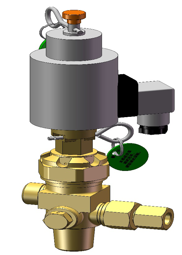
Figure 6 Nitrogen Discharge Valve
2.2.2 Four in One Valve(Figure 7)
This Valve is combined by Low discharge high seal valve(figure8),Signal feedback valve(figure 9),Oil and gas isolation valve and flow control valve(figure 10)。 It can effectively isolate oil and gas, accurately feedback nitrogen injecting signal, adjust nitrogen flow, and release micro-leakage gas in time。

Figure 7 Four in One Valve
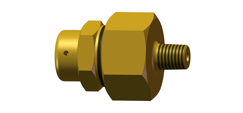
Figure 8 Low Discharge High Seal Valve
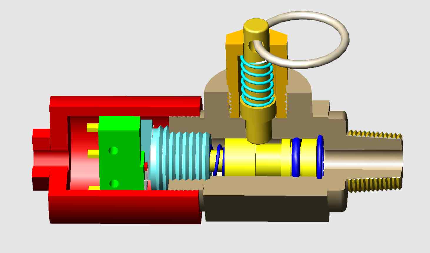
Figure9 Signal Feedback Valve
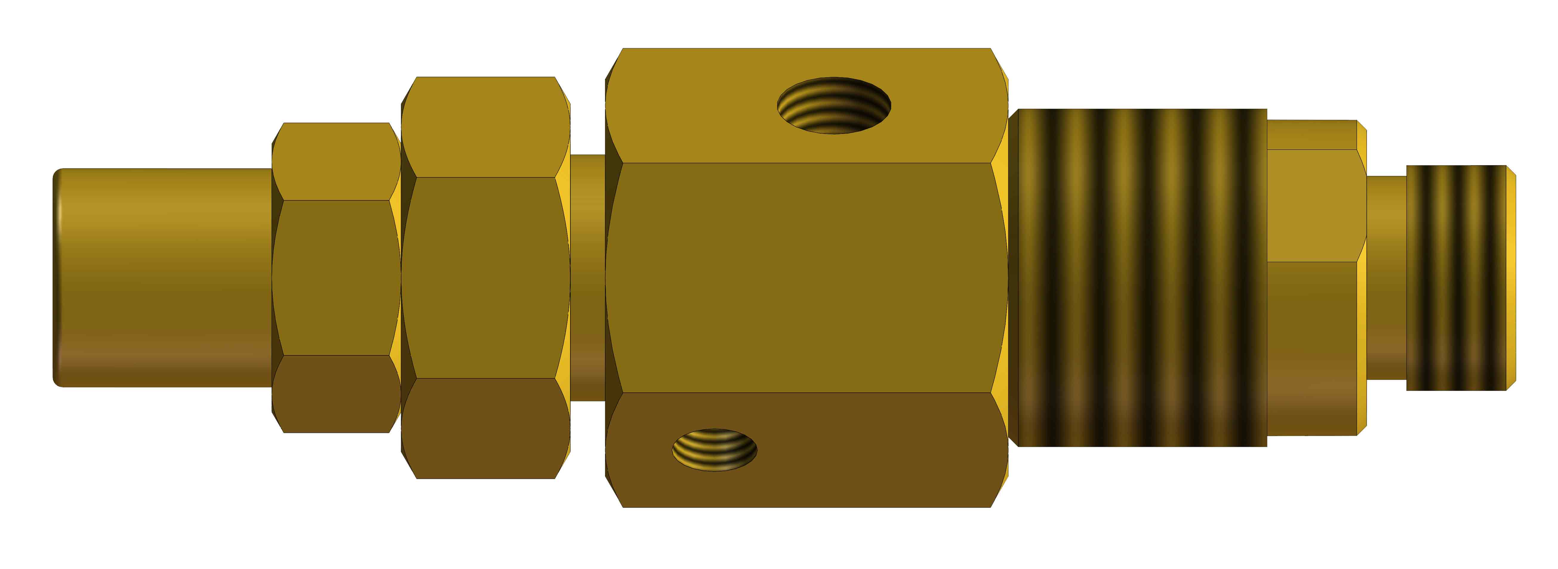
Figure 10-1:Flow Control Valve Figure10-2:Oil-gas Isolation Valve
2.3 Control Cabinet
Control Cabinet is installed in the main control room of the transformer or the fire control room, which is the core part of the whole system. It collects the relevant information of the system through the sensors, and is responsible for providing the signal indication of the working state of each part, fault alarm signal indication and starting the nitrogen injection program instruction.
Control system has three different modes: automatic, stop and manual. The automatic mode can analyze, judge and command the operation of the TEFPE system by collecting sensor signals under unattended condition. The manual mode enables the nitrogen injection system to be activated directly in case of emergency, when the fire alarm is confirmed.
Control Cabinet can be composed of several control hosts, each of which is connected to a fire protection equipment controlling a transformer, and a control cabinet can contain up to 4 independent control units.

Figure 11 Control Cabinet
Note: 1. Control Cabinet color can be specified by the customer (If there is no special specified, we recommend: RAL7032)
2. Front gate is glass for observation, back door should be locked after maintenance..
3. The power supply shall use uninterruptible power supply.
2.4 Decompression Devices
2.4.1 Decompression Devices
Decompression Device is the main component of the TEFPE system. Its main function is to release the high speed shock wave pressure generated by arcing inside transformer to prevent transformer explosion. We developed many types to meet all kind of transformers or oil-immersed electrical equipment.
2.4.1.1Horizontal Decompression Device
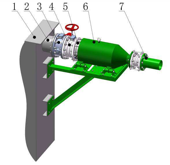
1. Transformer Oil Tank Wall
2. Connection Pipe
3. Isolation Valve
4. Corrugated Pipe
5. Rupture Disk Set
6. Decompression Chamber
7. Oil Evacuation Pipe
2.4.1.2Vertical Decompression Device

1. Oil Outlet
2. Decompression Chamber
3. Rupture Disk Set
4. Corrugated Pipe
5. Isolation Valve
6. Connection Pipe
7. Transformer Top Cover
Figure13 Vertical Decompression Device
2.5. Explosion-Proof Rapid Pressure Relief Device
This is a new invention of explosion-proof type rapid pressure release device. Its internal structure, contains a spring mechanism and explosion-proof Rupture Disk device, therefore, it has the functions of the traditional pressure release valve and Rupture Disk:
Not only can release the static pressure whose growth rate is not very fast, and reset automatically after pressure relief;
But also has the function of high speed pressure relief. In case of high speed dynamic pressure caused by arc fault, it can open the pressure relief channel of Rupture Disk and release the shock wave pressure instantly.
It is the ideal device of the latest generation to completely prevent the transformer explosion.
The outline structure of rapid explosion-proof pressure relief device are shown in FIG. 18 and FIG. 19.
Figure 18 shows the DN150 rapid explosion relief device, which is generally used to protect OLTC.
The rapid explosion relief device (figure 19) is generally used for the explosion-proof of the transformer main tank and Oil Cable Bushings.
The commonly used specifications are DN150, DN200, DN250 and DN300.

Figure18 DN150 Rapid Explosion Relief Device
1 Oil Inlet 2 Oil Outlet 3 Gas Outlet 4 Signal Rob for spring system
5 Signal connection port for spring system 6 Signal connection box for rupture disk
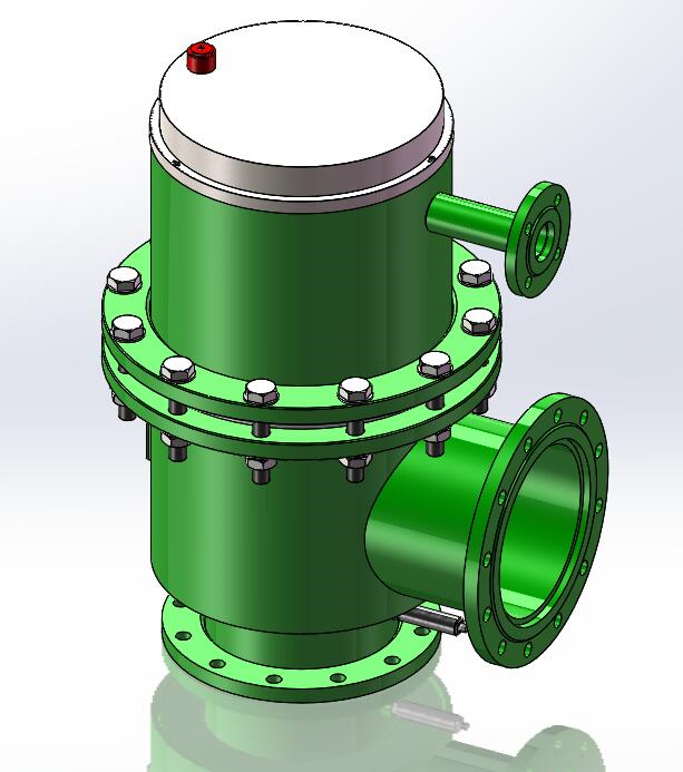
Figure19 Quick Pressure Relief Device
2.6 Oil and Gas Separation Tank
The main function of the Oil and Gas Separation Tank is that after the failure of the transformer, the oil and gas mixture ejected by the Rupture Disk burst is separated in the tank according to their respective specific gravity. The gas separated is continuously diluted by nitrogen injection, and then discharged into the atmosphere through the exhaust pipe at the top of the oil and gas separation tank.
Depending on the transformer configuration or customer requirements, there are the following types of oil and gas separation tanks.
2.6.1Wall mounted:
It is mounted on the firewall. It weighs about 600 kilograms when filled with oil. The designer shall calculate the maximum bearing capacity of the firewall. The bottom of the oil and gas separation tank is usually higher than the top of the transformer oil conservator.
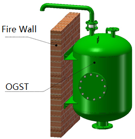
Figure 20
Wall-mounted OGST
2.6.2 卧式油气分离罐:
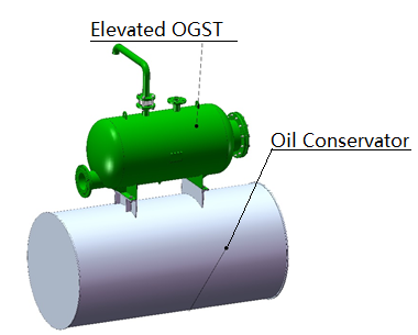
Elevated Oil and Gas Separation Tank is mounted on the top of the oil conservator. It weighs about 600 kilograms when filled with oil. In the production of oil pillows, the weight and joint support need to be considered.
2.6.3 Parallel Oil and Gas Separation Tank (also known as sliced type)
Install side by side with Oil Conservator.
It weighs about 600 kilograms when filled with oil. Usually made with oil conservator.

Figure22 Parallel Oil and Gas Separation Tank
2.6.4 Floor Oil and Gas Separation Tank
Oil and gas separation tanks are installed on the ground. The volume should consider the oil discharged by the transformer. Normally the volume is 3000-6000L.
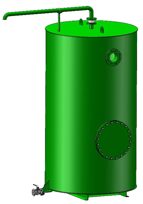
Figure23 Floor Oil and Gas Separation Tank
· 4. Instructions for model and specification

Common specifications and models:
BPZM-40×2-ZRH-FB1 Used to protect the main tank
BPZM-40×3-ZRH-FB2 Used to protect main tank and OLTC (on-load tap changer)
BPZM-40×3-ZRH-FB3 Used to protect main tank, OLTC and Oil Cable Bushings